Practical application guide · Examples are illustrative unless identified as catalog data.
Length measurement and probing answer different questions
The PeakMerit catalog uses MPEe for maximum permissible length measurement error and MPEp for probing performance evaluated using a reference sphere. Read them together with the measuring mode, configuration and applicable test procedure. A probing specification should not be treated as the length error of the whole machine.
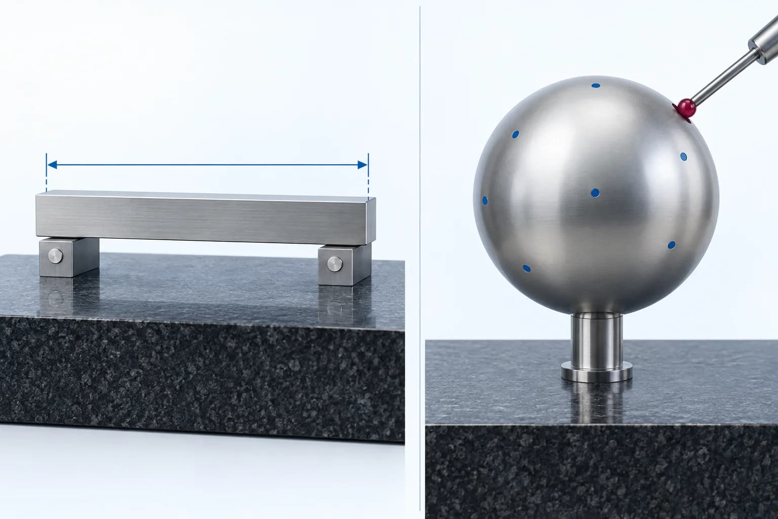
Compare a measured length with a known reference.
Evaluate probing using a reference sphere.
Concept illustration · These are different checks. The artwork does not show a prescribed test procedure, test result or scale relationship.
| Term | What to look for |
|---|---|
| MPEe | The length-dependent error formula and the unit used for L. |
| MPEp | The probing error limit, sphere test procedure and stylus configuration. |
| Measuring mode | The separate scanning or touch-trigger specification for the exact model. |
Worked example: Gemini 565 in scanning mode
The published Gemini 565 scanning entry lists MPEe = (0.9 + L/300) µm and MPEp = 1.1 µm, with L in millimeters. For a 300 mm measured length, substitute 300 into the length formula:
This 1.9 µm value is the catalog length-error limit at that length, not a measured result or a part-specific uncertainty. The example uses scanning-mode data; the touch-trigger entry has different values. Gemini is intended for a controlled quality room. Confirm the temperature limits, temperature variation, probe and stylus setup, and acceptance procedure in the final quotation and acceptance documentation; those conditions cannot be inferred from this calculation.
The table is arithmetic from the published formula, not measured test results. Enter L in millimeters; the resulting limit is in micrometers. The calculation does not establish performance at every location, orientation or stylus arrangement.
| Illustrative measured length | Substitution | Calculated MPEe limit |
|---|---|---|
| 100 mm | 0.9 + 100/300 | 1.23 µm (rounded) |
| 300 mm | 0.9 + 300/300 | 1.90 µm |
| 500 mm | 0.9 + 500/300 | 2.57 µm (rounded) |
Apply the number to a drawing review
For an illustrative 300 mm dimension on a customer drawing, record 1.9 µm as the catalog comparison value for this model in scanning mode. Next request the measurement method and task-specific uncertainty for that characteristic. Dividing a drawing tolerance by this MPE alone does not establish whether the inspection process is suitable.
Keep the measuring modes separate. The same Gemini 565 entry lists touch-trigger MPEe = (1.6 + L/300) µm, which calculates to 2.6 µm at 300 mm. These are mode-specific catalog limits, not an experimental comparison of two routines on your part. The lower catalog value does not replace an application trial.
Accuracy, repeatability and uncertainty
Repeatability describes how closely repeated results agree under the same conditions. A measurement process can repeat closely while retaining a systematic error. Measurement uncertainty describes the dispersion reasonably attributed to the measurement result and depends on the particular task. Neither is interchangeable with a catalog MPE.
Part temperature, material expansion, fixturing, stylus reach and measurement strategy all belong in the application review. Compare machines at relevant measurement lengths and under comparable conditions, then agree how the actual inspection requirement will be demonstrated.
A close grouping does not tell you how close the results are to a reference value.
Tight grouping, with an offset
Repeated results are close together, but displaced from the reference. Tight repeatability can coexist with bias.
Wider grouping, around the reference
Results fall on both sides of the reference, with more variation between repeats.
- Identify the exact model and probing mode.
- Check the required length and probing specifications separately.
- Confirm environmental and probe-configuration conditions.
- Agree the acceptance method and task-specific evidence.
Turn the comparison into an acceptance brief
Prepare two deliverables: evidence that the supplied CMM meets its agreed specification, and evidence that your planned measurement process is suitable for the part. Use the drawing and intended fixture to define the second deliverable before commissioning.
Formal test reports can use more detailed symbols than a product table. Request the relevant ISO 10360 part and edition, the tested configuration and the definition of each reported quantity. Do not assume that every number headed 'accuracy' was established by the same test.
Connect machine verification with evidence for the work you actually need to measure.
CMM specification
Model · measurement mode · test conditions
Your part
Drawing · fixture · measurement strategy
- Name the model, probe, stylus arrangement, controller and software configuration.
- Record the length and probing limits with their test methods and conditions.
- Identify critical drawing characteristics and how each will be demonstrated.
- Request the test report, reference-artifact traceability and uncertainty information.
- Agree how results close to a tolerance limit will be accepted or rejected.
- Document checks and review intervals to use after installation.